 Rodless cylinders OPL
Features
The cylinder barrel of extruded anodized aluminium has a slot along its entire length. To provide rigidity, the bore is eccentric to the outside diameter. A flexible corrosion resistant steel inner band running along the entire length of the bore and passing through the piston provides a near-zero-leakage metal to metal seal. An outer band of the same material acts as a cover over the slot preventing foreign particles to enter into the cylinder. The aluminium piston is fitted with synthetic bearing rings and houses the internal magnet. A physical connection through the slot between the piston and the external mounting plate allows the power transmission outwards. This solid connection permits the acceptance of big external forces and moments, and minimizes frictional losses.
Magnetic switches can be mounted on the aluminium profile with mounting brackets.
The cylinder is available in seven sizes: ø16; 25; 32; 40; 50; 63; 80.
Two versions are available: the basic version (part number begins with OPL), suitable for small and medium loads, and the version with recirculating ball bearing guide (part number begins with OPL-KF), suitable for big loads and precision.
|
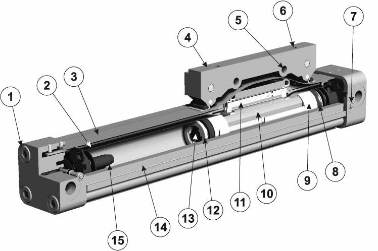
1. Vite per assemblaggio testata Screw for assembling cylinder head 2. Nastro interno di tenuta, in acciaio resistente alla corrosione Corrosion resistant steel inner sealing band 3. Nastro esterno di tenuta, in acciaio resistente alla corrosione Corrosion resistant steel outer sealing band 4. Piastra standard per il montaggio del carico esterno Standard mounting plate for external loads 5. Foro passante per il fissaggio del carico esterno Passing-through hole to fasten the external loads 6. Fori filettati per il fissaggio del carico esterno Threaded holes to fasten the external loads 7. Vite di regolazione ammortizzo Screw for adjustable end cushoning |
8. Guarnizione di tenuta del pistone Piston sealing 9. Anello guida, in materiale a basso attrito Bearing ring, low friction material 10. Magnete permanente Magnet 11. Pattino di scorrimento Slide shoes 12. Pistone Piston 13. Guarnizione di ammortizzo Cushion seal 14. Camicia: profilo estruso con cave per il montaggio dei sensori Cylinder barrel: extruded profile with grooves for magnetic sensors 15. Cono di ammortizzo Cushion pipe |
|
mod. OPL | mod. OPL-KF |
| model | bore | theoretical action force at 6 bar [N] | real action force at 6 bar [N] | maximum load [N] | max. moment [Nm] | ||
|
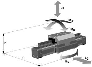
F
|
Fa
|
L
|
Ma
|
Ms
|
Mv
|
||
|
OPL
|
16 | 120 | 78 | 120 | 4 | 0.3 | 0.5 |
| 25 | 295 | 250 | 300 | 15 | 1 | 3 | |
| 32 | 483 | 420 | 450 | 30 | 2 | 5 | |
| 40 | 754 | 640 | 750 | 60 | 4 | 8 | |
| 50 | 1178 | 1000 | 1200 | 115 | 7 | 15 | |
| 63 | 1870 | 1550 | 1650 | 200 | 8 | 24 | |
| 80 | 3016 | 2600 | 2400 | 360 | 16 | 48 | |
| model | bore | maximum speed [m/s] | maximum load [N] | max. moment [Nm] | |||
|
v
|
L1
|
L2
|
Ma
|
Ms
|
Mv
|
||
|
OPL-KF
|
16 | 3 | 1000 | 1000 | 25 | 12 | 25 |
| 25 | 5 | 3100 | 3100 | 90 | 35 | 90 | |
| 32 | 5 | 3100 | 3100 | 133 | 44 | 133 | |
| 40 | 3 | 7100 | 4000 | 346 | 119 | 346 | |
| 50 | 5 | 7500 | 4000 | 480 | 170 | 480 | |
| total lenght of cylinder barrel | cylinder bore | ||||||
| 16 | 25 | 32 | 40 | 50 | 63 | 80 | |
| 0 ... 1000 mm |
+1.8 -0 |
+1.8 -0 |
+1.8 -0 |
+1.8 -0 |
+1.8 -0 |
+1.8 -0 |
+1.9 -0 |
| 1001 ... 2000 mm |
+1.9 -0 |
+1.9 -0 |
+1.9 -0 |
+1.9 -0 |
+1.9 -0 |
+1.9 -0 |
+2 -0 |
| 2001 ... 4000 mm |
+2.1 -0 |
+2.1 -0 |
+2.1 -0 |
+2.1 -0 |
+2.1 -0 |
+2.1 -0 |
+2.2 -0 |
| 4001 ... 6000 mm |
+2.3 -0 |
+2.3 -0 |
+2.3 -0 |
+2.3 -0 |
+2.3 -0 |
+2.3 -0 |
+2.4 -0 |
| > 6000 mm |
+2.8 -0 |
+2.8 -0 |
+2.8 -0 |
+2.8 -0 |
+2.8 -0 |
+2.8 -0 |
+2.9 -0 |
| type | bore | weight of cylinder stroke 0 | add per 100 mm of stroke | weight of carriage * |
| OPL | 16 | 0.25 kg | 0.1 kg | - |
| 25 | 0.74 kg | 0.197 kg | - | |
| 32 | 1.62 kg | 0.354 kg | - | |
| 40 | 2.10 kg | 0.415 kg | - | |
| 50 | 3.74 kg | 0.566 kg | - | |
| 63 | 6.12 kg | 0.925 kg | - | |
| 80 | 12.42 kg | 1.262 kg | - | |
| OPL-KF | 16 | 0.558 kg | 0.21 kg | 0.228 kg |
| 25 | 1.522 kg | 0.369 kg | 0.607 kg | |
| 32 | 2.673 kg | 0.526 kg | 0.896 kg | |
| 40 | 4.167 kg | 0.701 kg | 1.531 kg | |
| 50 | 7.328 kg | 0.936 kg | 2.760 kg |
| max. piston speed at cushoning start |
 |
| cushionable mass |
| bore | cushion length [mm] |
| 16 | 11 mm |
| 25 | 17 mm |
| 32 | 20 mm |
| 40 | 27 mm |
| 50 | 30 mm |
| 63 | 32 mm |
| 80 | 39 mm |
carriage in up position | 1 = OPL-KF16 2 = OPL-KF25 3 = OPL-KF32 4 = OPL-KF40 5 = OPL-KF50 | 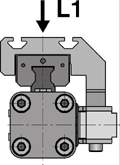 |
carriage in side position | 1 = OPL-KF16 2 = OPL-KF25 3 = OPL-KF32 4 = OPL-KF40 5 = OPL-KF50 | 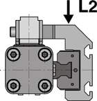 |