Inversore di carico per cilindri senza stelo serie OPL Inversion mounting for rodless cylinders OPL
alesaggio bore
sigla part number
32
3510
alesaggio bore
sigla part number
40
4510
50
5510
63
6510
80
8510
ø
K
L
M
N
P
øR
S
T
X
Z
BC
32
140
60
60
-
-
7
-
-
90
-
160
40
110
55
61
49
57
7
28
18
90
M6
138
50
140
70
69
57
65
7
28
18
110
M6
168
63
180
90
83
68
78
9
30
19
140
M8
208
80
240
120
101
83
95
11
32
20
180
M10
268
ø
BE
BF
BG
BH
BJ
BK
BL
CA
CB
CD
ZZ
a
32
58
-
44
-
33
-
-
M8
25
20
-
-
40
85
58.5
73
81
53
42
48
-
-
-
12
22°
50
97
70
85
93
62
50
56
-
-
-
12
18°
63
117
82
102
112
77
62
71
-
-
-
16
15°
80
143
102
125
137
96
78
88
-
-
-
20
15°
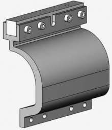
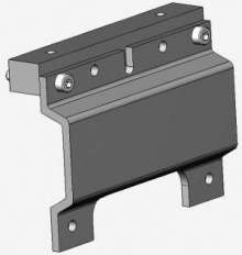
In ambienti sporchi o nel caso di particolari problemi di spazio si raccomanda di collocare il cilindro sottosopra. Questo accessorio per linversione di carico sposta lapplicazione del movimento sul lato opposto del cilindro. La dimensione e linterasse dei fori di fissaggio del carico sono uguali a quelli del cilindro standard.
Gli altri componenti come il supporto intermedio e i sensori magnetici possono essere montati sul lato libero del cilindro.
In dirty environments, or where there are special space problems, inversion of the cylinder is recommended.
The inversion bracket transfers the driving force to the opposite side of the cylinder. The size and position of the mounting holes are the same as on the standard cylinder.
Note: other components such as mid-section supports, magnetic switches can still be mounted on the free side of the cylinder.
 Inversore di carico