 Sensori per cilindri pneumatici
 |  |
 |


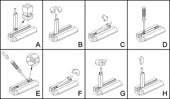
| Istruzioni per lĺinstallazione: A. Inserire dallĺalto il sensore come indicato in figura B. Ruotare di 90░ il corpo del sensore C. Alloggiare il sensore nella cava tenendo in vista il taglio del grano D. Individuare la posizione di lettura, quindi avvitare il grano Istruzioni per la rimozione: E. Una volta allentato il grano, agire sul dentino di blocco posteriore F. Contemporaneamente sollevare il sensore aiutandosi con il cavo G. Ruotare di 90░ il corpo del sensore H. Estrarre il sensore dalla cava | Instructions for installation: A. Insert the sensor from above as indicated in the image B. Rotate the body of the sensor by 90░ C. Put the sensor in the groove keeping the head of the screw in sight D. When the reading position has been found, tighten the screw Instructions for removal: E. Loosen the screw and apply pressure on the back fixing element F. At the same time lift the sensor using the cable for help G. Rotate the sensor by 90░ H. Remove the sensor from the groove |
| CILINDRO | STAFFA [mounting bracket] |
|
microcilindri ISO 6432 minicylinders ISO 6432 |
°10: 26.039.0 °12: 26.040.0 °16: 26.041.0 °20: 26.042.0 °25: 26.229.0 clicca qui per disegno |
|
cilindri tondi round cylinders |
°32: 26.230.0 °40: 26.231.0 °50: 26.232.0 |
|
cilindri compatti compact cylinders |
su cava a T : montaggio diretto su cava a coda di rondine : 26.147.0 |
|
cilindri corsa breve short stroke cylinders |
26.147.0
|
| cilindri ISO 6431 °32 ... 125 |
montaggio diretto direct mounting |
| cilindri ISO 6431 °160 ... 200 | 26.219.2 |
|
cilindri ad asta gemellata twin rod cylinders |
montaggio diretto direct mounting |